We design software, we try to describe its design and related information; The collective knowledge can be described in terms of words (document), visual (diagram), or demonstration.
In the internal description of an application, a single representation of an architectural view cannot meet the eyes of all associated various skilled stakeholders (Management, Infrastructure Operators, Product Managers, Developers, Business Executors).
Each stakeholder is only interested in a portion of the software information.
Philippe Kruchten defined 4+1 Views Model to capture the description of Software Implementation or Architecture intomultiple concurrent views. A ViewModel is a subpart of the overall software implementation description knowledge and targets a subset of the audience.
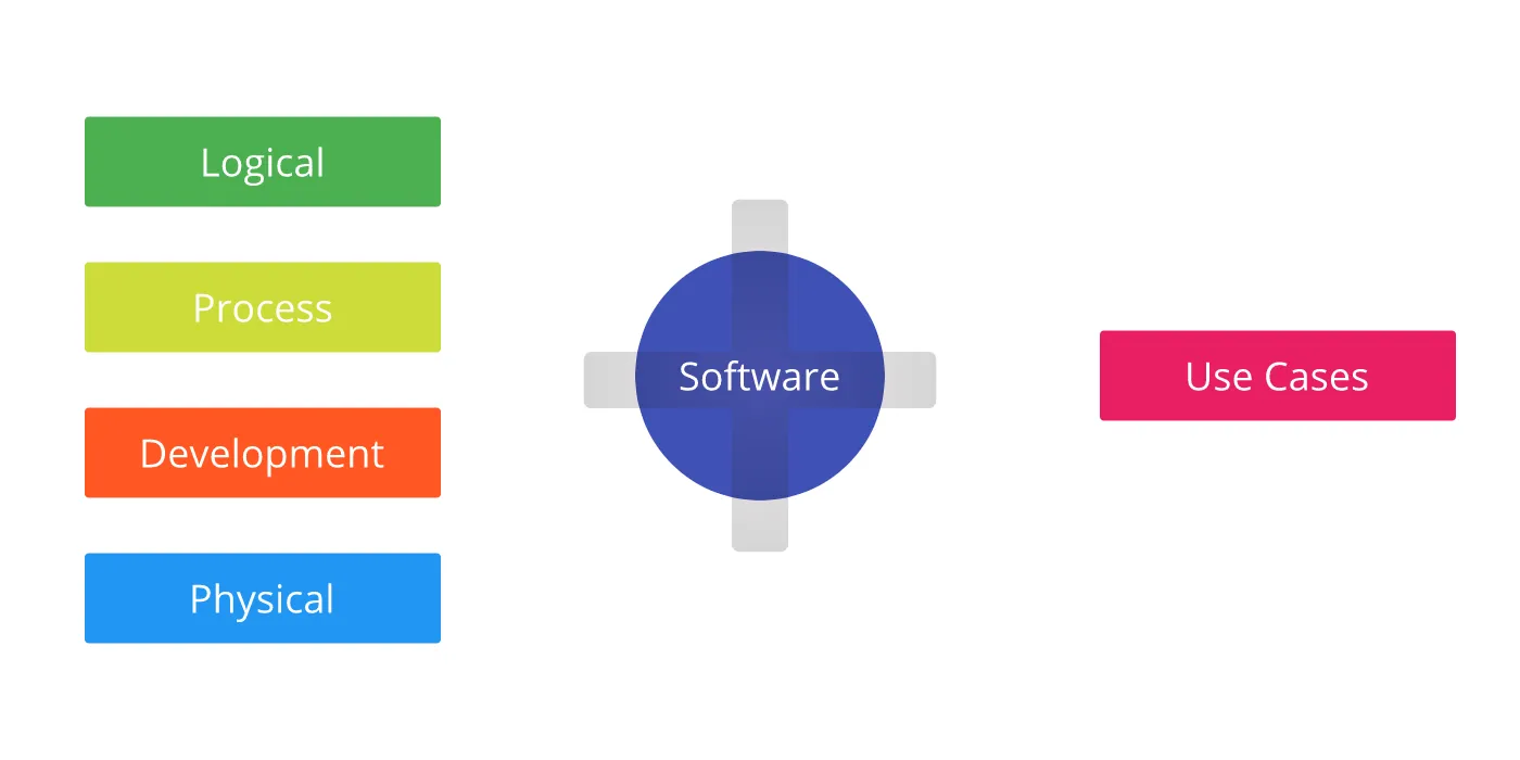
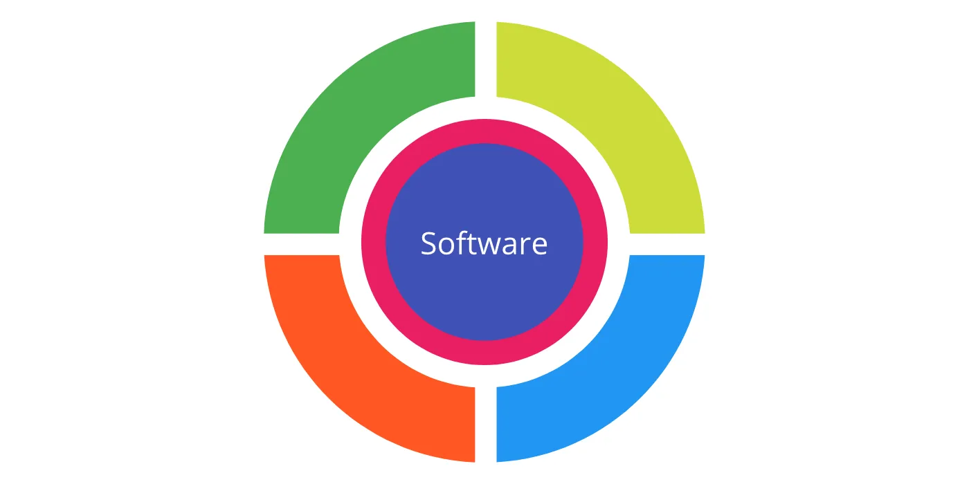
4+1 Views Model
4+1 views model is an information organization framework; it includes logical, process, development, physical layout and end-user perspective information of an application.
A view is an aspect (subpart) of information. A notion is a way of representing information.
A single type of notation is usually used in multiple views. Views do not enforce any notion.
Logical View
Logical View captures the functional requirements of the application as decomposition of structural elements or abstractions.
For Developers, Engineer Managers,…
- Object Decomposition is capturing of application behavior into classes and packages. It is the base of functional analysis in case of Object-Oriented Paradigm.
Classes and packages may be represented using UML Class Diagrams and UML Package Diagrams, respectively.
- Data Modelling is the analysis of data gathering and organizing data into logical entities.
ER diagram is a well-known notation to represent business entities and relationships.
- System and subsystems view is breaking down of application into modules and arrangement of their responsibilities and relationships.
UML Component diagram can be used.
Process View
- States Transition can be used to understand state and transition in case of a workflow-based system.
UML State Diagram is used to represent state and state transitions.
- Information Flow represents information routing from one entity to another entity.
Data Flow Diagram (DFD), Application Prototype (UX), UML Activity, and UML Sequence diagram represent the various flow information levels.
Process Decomposition represents runtime partitioned application decomposition. It can be called Service Decomposition for network partitioned processes.
Non-functional aspects like Throughput, Availability, and Concurrency. These are easier to put in words than in diagrams.
Development View
Development View focuses on the management of an application.
For Management & Developers
- Teams Organization — Roles and Responsibilities of team members
- Development Methodology is a way of development workflow implementation. Agile Methodologies are popular these days.
Tip: It is crucial to have agility than Agile Framework.
Popular Agile Methodologies Framework: Scrum, XP, Kanban.
- Development Standards — Set of guidelines & coding standards, automation tools.
e.g. VCS System and their branching system, CI, Deployment Automation, Code Linting, Code Style
- Test Planning of functionalities.
How do you test? Automation or Manual or hybrid? What do you test? Scope of test? How do you record test step sequences?
Work logs and Tracker system to manage and track tasks.
JIRA, Asana, Harvest are popular commercial tools.
Road-maps give ideas about deliverables.
Physical View
Physical View represents the deployment layout or infrastructure of an application. In essence, it captures hardware mapping of application components or processes.
For DevOps, EMs, Software Engineers
Topology Architecture | Deployment Plan The cluster of application instances and their places in the geography of physical or virtual machines available.
UML deployment diagram, Network diagram are standard options.
System Capacity of the application
Configuration Management
Tip: It is essential to keep configuration out of the application and build a workflow to change the configuration to have a higher degree of observability and flexibility.
Use Cases
Use Cases captures an End-User Perspective into a systematic, logical information structure. It complements all other views and is used to validate them.
For Every Stakeholder
Stories are used for elaboration; It may be a combination of textual documents with or without UML Sequences, Actor diagrams, Prototypes.
Closing Notes
4+1 Model Views covers much of the software if done right. It is not rigid; you can skip any view or subview that does not add any value in expressing your software design.
4+1 Views Model is too result-oriented. Views only represent the results of decisions that may not be evident over time or to the people who were not part of the original design discussion. This problem can be solved, including an additional view called Architecture Decision View (ADR).
Architecture Decision View
Architecture Decision View captures contextual knowledge behind any architectural decision. It focuses on causation and circumstances that lead to decisions.
Architecture Decision Record (ADR) is one of the implementations which can be found at: https://github.com/joelparkerhenderson/architecture_decision_record
The Original Paper
You can also read the original paper of 4+1 Views Model at: https://www.ics.uci.edu/~andre/ics223w2006/kruchten3.pdf
There are other documentation frameworks too:
- Arc 42 — https://arc42.org/overview/